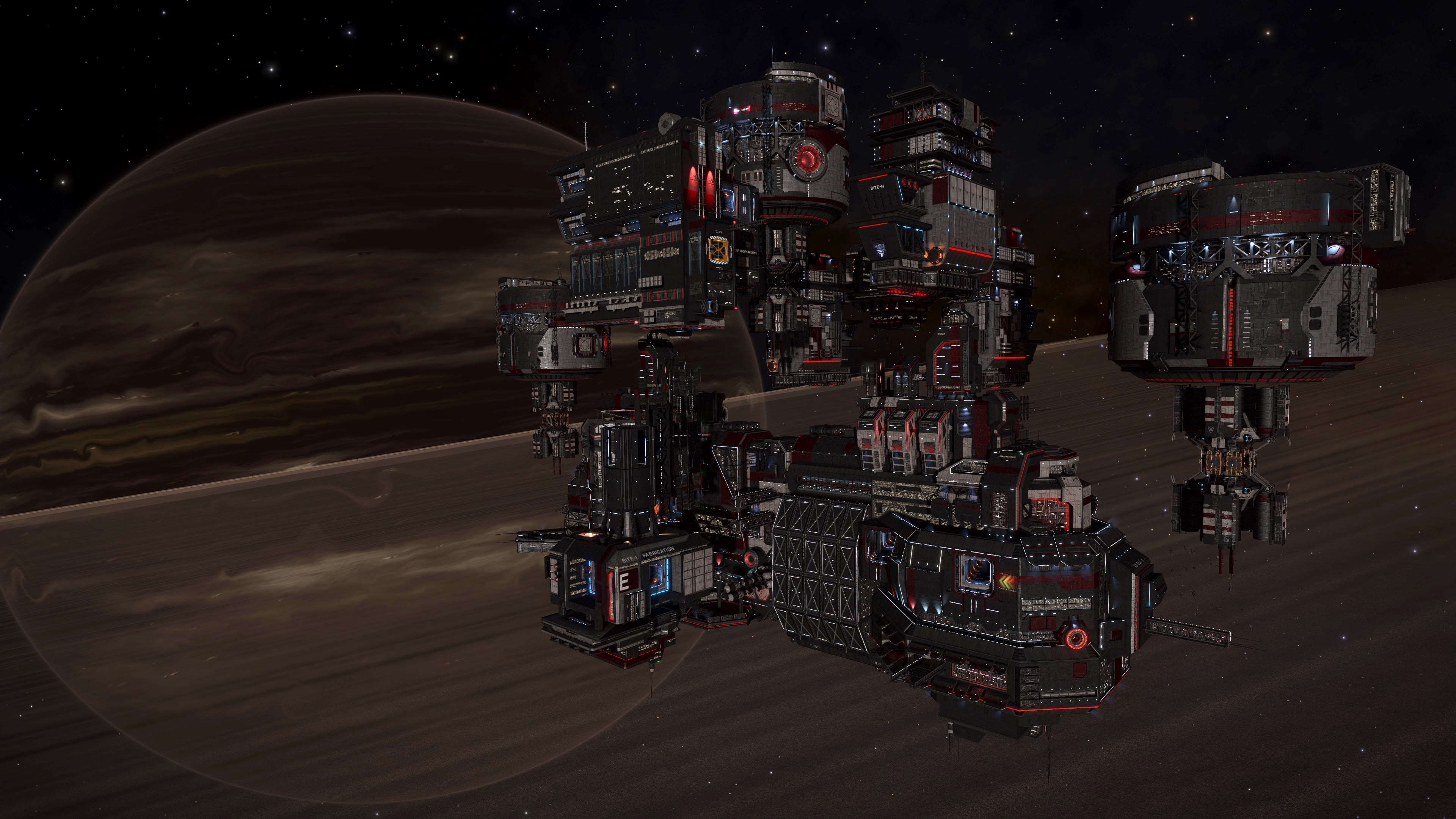
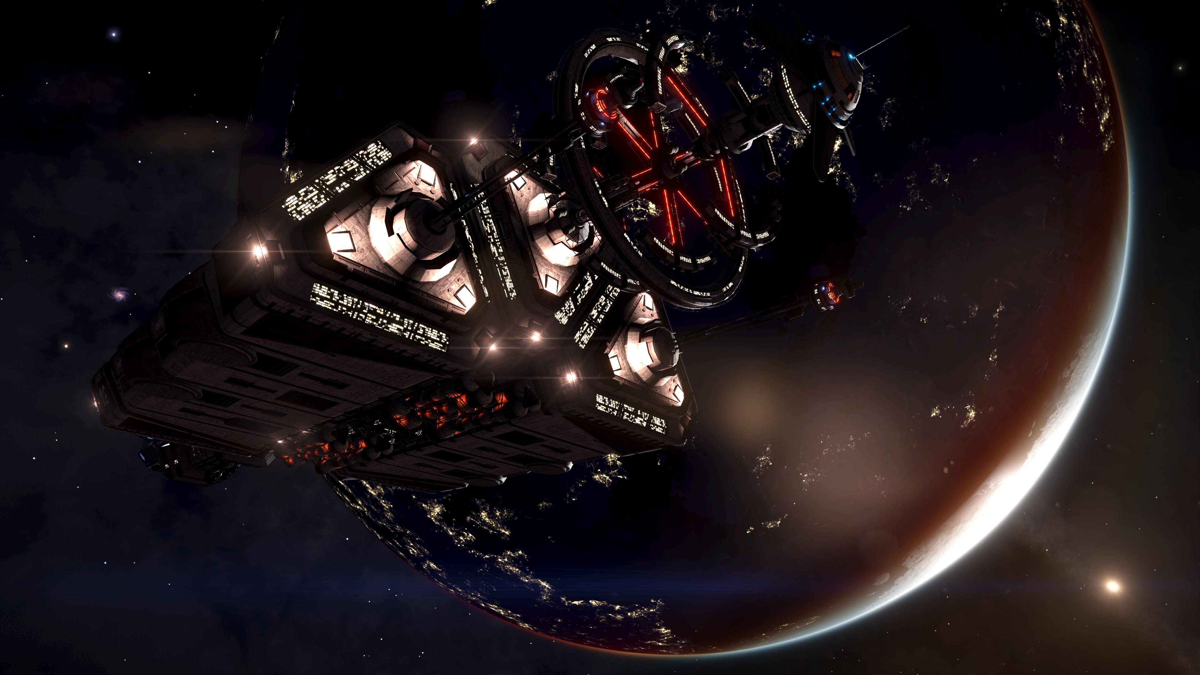
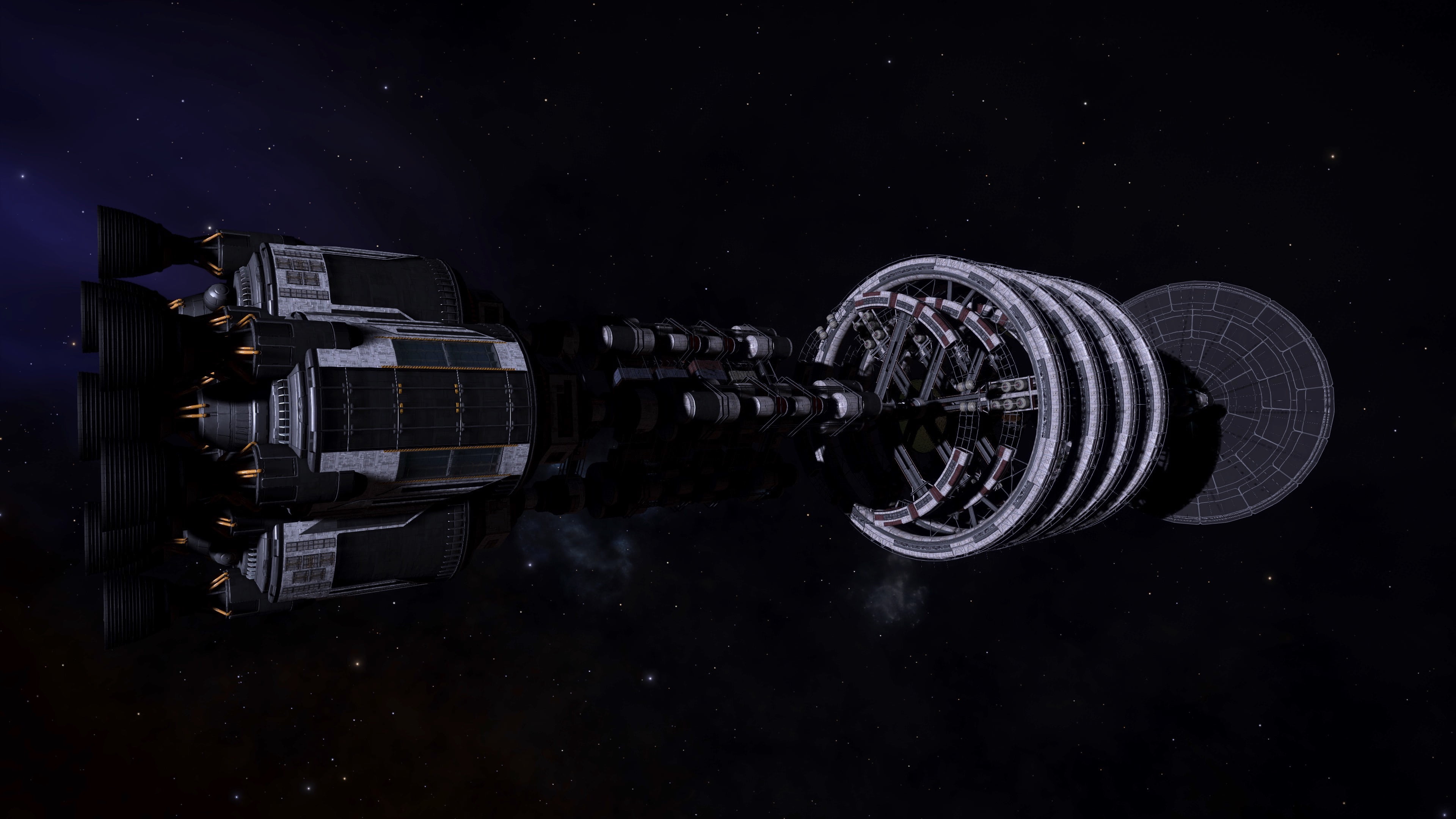
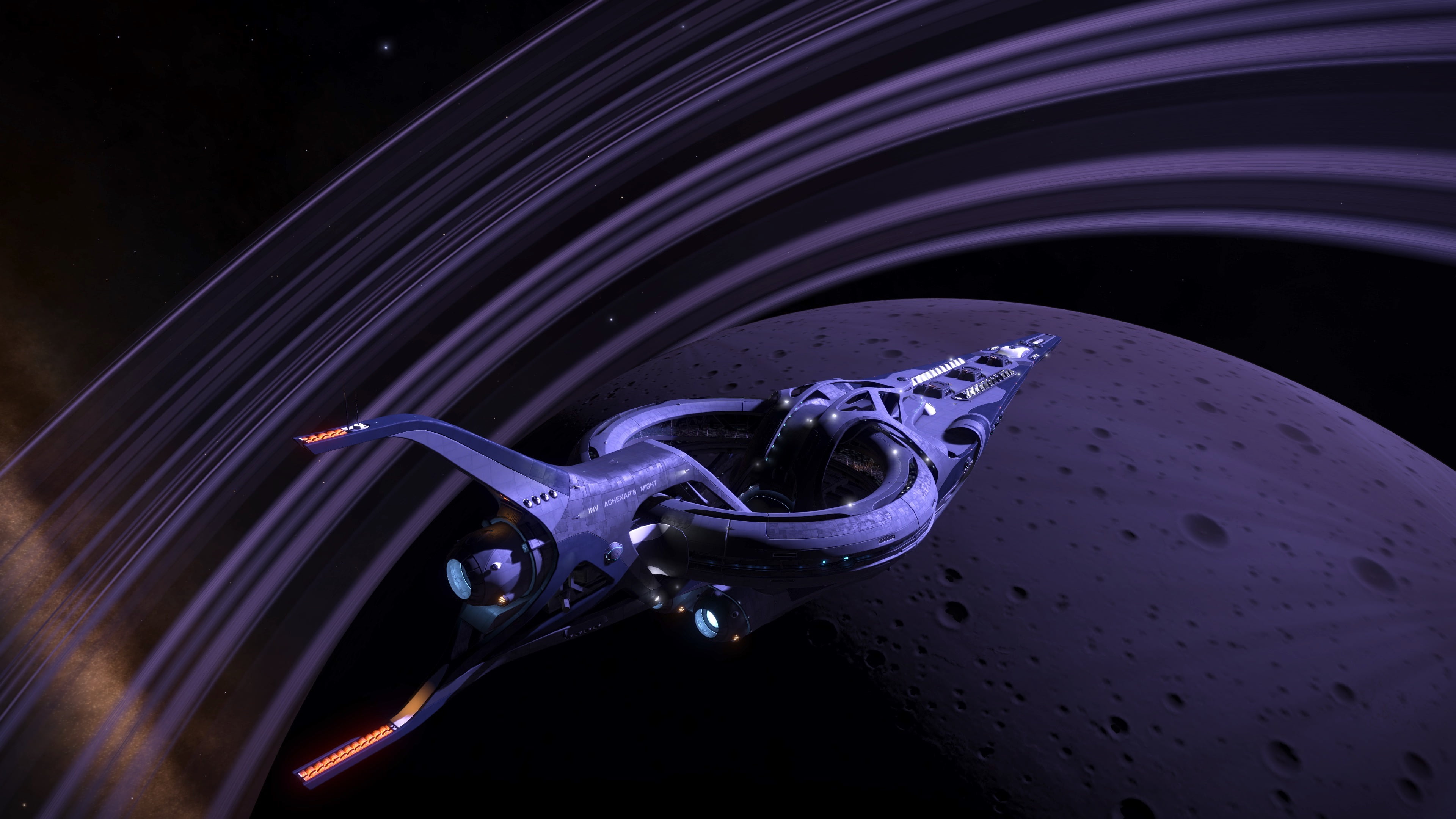
With the release of the Odyssey branded software upgrade to the Commanders of the Pilots Federation’s fleet of ships, they are now capable of atmospheric flight. Although to-date, only tenuous atmospheric entry is allowed by the software, this brings into question the potential future of such updates and whether or now denser atmospheres will one day be allowed. In anticipation for this, Canonn Interstellar Research has embarked on an early study of the aerodynamic characteristics of these ships to aid the Pilots Federation in determining what ships, if any, are best suited for atmospheric flight and what sorts of updates may be required to allow these ships to safely enter denser atmospheres.
Nomenclature

Introduction
While our ships bad been locked by the Pilots Federation to operate only in the vacuum of space, with the release of the Odyssey branded software upgrade, Commanders are now able to enter tenuous atmospheres and fly within them. While the software currently limits these vehicles to entering atmospheres with 0.1 atmospheres, 10132.5 Pascals, or less of surface pressure, it now brings to question the impact of aerodynamics on these ships. While some may limit the amount of force and temperature placed on their surface structure through the use of shields, not every ship is shielded and would be fully exposed to these effects. This study aims to assess the aerodynamic characteristics of the fleet of ships made available by the Pilots Federation. This will aid in quantifying which may be more suited for aerodynamic flight and which may require some form of “atmospheric flight kit” to upgrade the outer mold line (OML) or flight-control systems to keep their pilots safe.
Process
Computational Fluid Dynamics (CFD) was used to assess the aerodynamic performance of the available ships. The academic and commercially available code Star-CCM+ was used due to it containing a full package of tools including geometry editing, meshing, solvers, and post-processing capability. Geometry was sourced from the 3D printing model website, Thingaverse, using models created by user Kahnindustries. The model was imported at full scale and cleaned up, i.e., made water0tight with minor surface edits to improve the stability of the CFD code. After cleanup, the model was meshed using a polyhedral mesher, which fills the volume domain with soccer ball like cells which generally keep at least one face orthogonal to the incoming flow. This type of unstructured mesh is useful on complex geometries where structured meshing would time prohibitive and where the flow direction is not uniform enough for a hexahedral mesh. Additionally, a prism layer mesher was used to place flat prismatic cells along the body’s surface to capture the boundary layer around the ship. Finally, the fluid physics were captured using a 3D steady Reynolds Averaged Navier-Stokes (RANS) coupled solver was used with a k-omega turbulence model. The models were selected for their stability across a wide range of flight conditions. While a multi-gas model could have been implemented to assess thruster/engine plume effects, the size of the study was already prohibitive and adding those models are computationally expensive and thus were not analyzed. For the working fluid, sea-level standard air treated as an ideal gas was used. While this does not match the low-pressure exotic gas environments seen across the galaxy, selecting only one gas limits the number of runs needed. A quick check of the Knudsen number was done to confirm that the continuum assumption would still hold on other atmospheres. The Knudsen number is a dimensionless number used to define the ratio of the molecular mean free path length to a representative physical length scale. For this check, the length of a Sidewinder MkI was used since it is the shortest ship and the Knudsen number is inversely proportional to a characteristic length. Shown below are two plots of the Knudsen number as a function of atmospheric pressure for the current hottest landable world with an atmosphere on record (2736.53K) and the coldest (20K). If the Knudsen number smaller than 0.01 the gas can be considered a continuum. As shown, for the hottest temperatures, the continuum assumption holds to about 1e-5 atmospheres (~1 Pascal) and for the coldest temperatures it holds past 1e-7 atmospheres (~0.01 Pascals). From this it is shown that the continuum assumption is valid even on the low-pressure exotic atmosphere worlds and conclusions of flight performance can still be drawn by running nondimensional characterization at sea-level standard conditions.

Once the methods and solvers had been identified, the next step was to select the flight conditions to input into the CFD code. Upon planetary interface, the shipboard software initiates a constant velocity glide at 2,500 meters per second which, depending on the gas composition of the atmosphere, can put atmospheric entry easily between Mach 7 and Mach 14. After the glide is complete, ships can easily cruise transonically and booster into supersonic speeds. As such, it is important to characterize the aerodynamic performance of these vehicles across the entire range from subsonic to hypersonic. To assess the performance across a range of flight velocities, four Mach numbers were selected to be representative of subsonic (Mach number < 1), transonic (Mach number ~1), supersonic (Mach number > 1), and hypersonic (Mach number ≥ 5) flight. Faster velocities are not needed since aerodynamics become independent of Mach number as Mach number goes to infinity. Mach number is defined by the following equation where |V| is the magnitude of the flight velocity, a is the speed of sound in the atmosphere, gamma is the ratio of specific heats of the gas, R is the specific gas consent, and T is the absolute temperature of the gas. To simplify this analysis, all runs were performed at sea level standard conditions, as previously stated, which defines the speed of sound as 340.2941 meters per second.

Due to the maneuverability of many ships, to make a full assessment of their performance characteristics would require a full sweep of angles of attack, angles of sideslip, and aerodynamic roll angles from 0 to 360 degrees. Due to the time cost probative nature of CFD, this study was limited to focusing on angles within the range of positive and negative 10 degrees angle of attack and sideslip and roll angles 0 to 45 degrees at a constant angle of attack. While this cannot be used to make a full aerodynamic database, it provides enough to assess the handling characteristics of these ships. Below is a list of conditions analyzed:
- Mach Numbers
- Subsonic: Mach 0.30
- Transonic: Mach 0.90
- Supersonic: Mach 2.00
- Hypersonic: Mach 5.00
- Angles of Attack
- At every Mach number listed above, -10 degrees to 10 degrees every 2 degrees at 0 degrees angle of sideslip.
- Angles of Sideslip
- At every Mach number listed above, 0 degrees to 10 degrees every 2 degrees at 0 degrees angle of attack. Due to all available ships being, for all intents and purposes, left-right symmetric only one side of the angles of sideslip need to be evaluated and the other side can be found through symmetry
- Aerodynamic Roll Angles
- At every Mach number listed above, 0 to 45 degrees every 9 degrees at a constant 6 degrees total angle of attack. Again, due to symmetry only one side of the roll polar needs to be evaluated and the other side can be found through symmetry.
To allow for comparison between flight conditions and ships, nondimensional parameters were used. For example, Mach number is a nondimensional parameter relating the speed of the vehicle through a gas to the speed of sound in said gas. As such, while two ships might be flying at different velocities through different gases, if the Mach numbers are the same the ships will experience the same shock angles and shock properties. Other key parameters for this analysis include pressure coefficient, force coefficient, and moment coefficient. The pressure coefficient is nondimensionalized as shown below where P_surf is the pressure on the surface, P_ref is a reference pressure (atmospheric pressure in this analysis), q is the dynamic pressure, rho is the atmospheric density, V is the freestream speed (flight vehicle speed), gamma is the ratio of specific heats of the gas, P is the atmospheric pressure, and M is the freestream Mach number (flight vehicle Mach number).

The force and moment coefficients are nondimensionalized as shown below where F is the total integrated force on the vehicle, M is the total integrated moment on the vehicle, S_ref is the reference area, b_ref is the reference span, and c_ref is the reference chord. Note that the rolling and yawing moments are lateral moments and the pitching moment is a longitudinal moment in the equations below.

By using the same reference area and length methodology between ships, a fair comparison can be made even if they are widely different sizes. For this study, the reference aera of a ship was taken as the projected frontal area. For pitching moment, the reference length (chord) was taken as the length of the ship. For rolling and yawing moment, the reference length (span) was taken as the width of the ship. As example is shown below. While forces can be measured anywhere along a given axis and remain constant, moments depend on the reference point around which they are taken. Since in flight all forces and moments act on the vehicle’s center of gravity (CG), it was decided to select that point as the moment reference center. The true CG of the ships had not been provided, but it was approximated using engineering judgement. For spacecraft, it is critical to center the lines of thrust around the center of gravity. This ensures that when the attitude control thrusters fire, they properly and fairly rotate the vehicle without producing adverse moments or translation. It is known the thrusters on these ships can operate at different thrusts, but it has been assumed that the CG would be centered between them in the event they all fired at maximum thrust. Under this assumption, the lateral CG must be located along the centerline of the ship, the longitudinal CG must be at the center of the forwardmost and aftmost attitude control thruster, and the vertical CG must be along the line of thrust of the main engine. All moments were taken about this approximated CG point.

As previously shown, an axis system is defined at the approximated CG and is oriented such that its X-axis points forward out the front of the ship, the Y-axis points out the right side, and the Z-axis points down. With respect to this axis system, flight angles are defined to analyze pitch, yaw, and roll motion. In the simplest sense, the angle of attack (alpha) is the angle with respect to the pitch plane, the angle of sideslip (beta) is the angle with respect to the yaw plane, and the aerodynamic roll angle (phi) is the angle with respect to the roll plane. These angles are shown below.

The loads were collected in the body axis aligned to the shown axis system. From these body loads, the wind axis loads can be derived. While the body loads are critical for finding the aerodynamic loading with respect to the airframe, the wind axis provides the aerodynamic parameters of lift and drag. Lift is the force perpendicular to the flow direction and is the force that counteracts the weight, keeping the ship aloft. If balanced the altitude remains constant. Drag is the force parallel to the flow that is pulling the vehicle back and counteracts the thrust of the engines. If balanced the velocity remains constant. The ratio of these two, the lift to drag ratio, can be considered a measure of aerodynamic efficiency, i.e., how good the vehicle is at lifting itself compared to how hard the gas is pushing back against it. Using the body axis loads and angles defined above, the wind axis lift and drag is defined below. Note these are the nondimensional parameters and that lift and drag are forces.

For comparing the forces acting on the vehicle, the lift and drag were be the primary parameters compared. For moments, all three (roll, pitch, and yaw) were evaluated to provide an assessment of vehicle stability. In terms of aerodynamics, stability is best described by what is known as the “Arrow Rule”. Simply put, if a vehicle is put at an angle of attack, angle of sideslip, or aerodynamic roll angle, and the forces on it cause a moment such that the vehicle wants to rotate to reduce those angles, the vehicle is considered stable. This is best illustrated by an arrow which has most of its mass located on the arrowhead (pulling the CG forward) and its aerodynamic surface (fletching) located on the rear. When an arrow is placed at an angle of attack, the aerodynamic forces will generate a moment that rotates the arrow to reduce its angle of attack. Thus, an arrow is aerodynamically stable as shown in the figure below.

While aerodynamic forces are generated from an integration of surface pressure, they can be assessed as if they are focused and placed at a point called the Center of Pressure (CP). As shown in the arrow rule, if the CP is behind the CG, the aerodynamic forces act as a restoring force, but if the CP is in front of the CG the aerodynamic force will increase the angle and act as a destabilizing force. The distance between the CG and CP is known as the Static Margin (SM). The static margin can be calculated using nondimensional parameters which results in a nondimensional distance typically referred to as calibers. This nondimensional distance can be multiplied by the reference chord or span, depending on the moment being analyzed, to return a dimensional distance between the CP and the CG. Reference span is used for the yaw plane static margin while reference chord is used for the pitch plane static margin. While this is an oversimplification, the static margin for the pitch plane can be found by assessing the derivatives of the pitching moment and body Z-force with respect to angle of attack and the static margin for the yaw plane can be found by assessing the derivatives of the yawing moment and the body Y-force with respect to eh angle of sideslip. This provides an axial distance between the CG and the CP for the Z-axis force and Y-axis force respectively. Recall that with the defined axis system, this means a positive static margin indicates the CP is in front of the CG resulting in an unstable airframe while a negative static margin indicates the CP is behind the CG resulting in a stable ship.

Another way to think about stability is to look at the slope of the moment curves. For pitching moment, if the slope is positive that means the pitching moment is increasing as angle of attack is increasing, meaning it will continue to pitch. Thus, a positive slope for pitching moment is considered unstable. For yawing moment, if the slope is negative that means that the yawing moment is becoming more negative as the angle of sideslip increases, meaning it will continue to yaw. Thus, a negative slope for the yawing moment is considered unstable. For rolling moment, if the slope is positive that means the rolling moment is becoming larger as the aerodynamic roll angle increases, meaning it will continue to roll. Thus, a positive slope for the rolling moment curve is considered unstable. Any point where the moment curves cross the zero axis indicate a point of aerodynamic trim, an angle which the airframe could sit at and not change its angle.

Note that an unstable airframe does not automatically disqualify a ship from being good aerodynamically. Unstable airframes are harder to fly and require advanced flight-control systems to ensure the nose stays pointed forward. For example, most 20th century fighter aircraft were unstable as being unstable allows for a more responsive and maneuverable airframe. Conversely, while stable airframes are easier to fly and will effectively “fly themselves” there is such a thing as too stable where the airframe becomes effectively ballistic and cannot maneuver.
Fleet Analysis
The Pilots Federation allows Commanders to purchase and fly 38 ships. These ships are broken into 3 general categories based on which standardized landing pad they fit on: small, medium, and large. Six manufactures have been certified to build and sell their ships to the Pilots Federation: Core Dynamics, Faulcon DeLacy, Gutamaya, Lakon Spaceways, Saud Kruger, and Zorgon Peterson. Each one of these ships has been evaluated. The following table holds links to separate pages for the analysis of each ship.
Conclusion
This study is not yet complete.
All results shown, particularly in reference to stability, are heavily dependent on the assumptions made. Aerodynamics are shape dependent; thus, it is important that the input geometry is as accurate as possible. It was noted that in some cases the geometry seemed highly tessellated potentially harming the airframe’s drag and lift characteristics. The CFD ran was coarsely meshed and ran to as few iterations as possible to reach reasonable convergence. This can hurt solutions especially in the transonic regime where the inherently unsteady flow needs many iterations to be averaged out. Finally, the location of the CG will directly impact the stability and if the CG location is drastically different some statements made regarding stability could be completely wrong. As with any study, bad data in results in bad data out. Care was taken to ensure that data used was as accurate as possible or assumed in as reasonable of a matter as possible so pending any findings this study makes up an initial assessment on the aerodynamic performance of spaceships.


